Airprop Ventilators
propeller fans
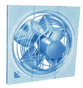
Wall mounted fans include both direct- and belt-driven fans with various impeller types. Use centrifugal exhaust fans for clean or contaminated air applications. Propeller style fans are available for exhaust, supply, filtered supply, and reversible applications. Airprop propeller fans cover a wide range of capacities. The five fan wheel types F, K, D53, NV, and type B cover a range in CFM of 3,000 to 250,000 and static pressures from free delivery to 1 Airprop fans range in size from 18” through 120” with varied arrangements of panels and ventilator wheels offered as standard units.
Airprop propeller fans cover a wide range of capacities. The five wheel types F, K, D53, NV, and type B cover a range in CFM of 3,000 to 250,000 and static pressures from free delivery to 1 Airprop fans range in size from 18” through 120” with varied arrangements of ventilator panels and wheels offered as standard fan units.
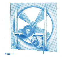
Bell drive, NV prop fan wheel has welded spider riveted to blades and standard flow, angle arm panel 24″-54″, channel arm panel 60″.
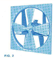
Direct drive, NV panel ventilator wheel has welded spider riveted to blades and reverse flow plate arm panel. 66″-72”.
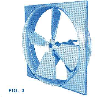
Belt drive, NV fan wheel has reflex fan blades, double orifice plate arm panel. Safety retaining plate is supplied with fans for vertical flow.
REFLEX FAN BLADES for NV ventilator wheels are available for all sizes 24” thru 96”. The trailing edge of the reflex fan blade is broken opposite to that of the standard NV fan blade. This reduces performance in both directions of air flow but results in a higher ratio of reverse to standard flow capacities than can be obtained with any other ventilator wheel. The reflex blade can be used to obtain equal capacity flow in either direction. Mounting the reflex wheel backwards in a single orifice fan panel will provide capacities of 85% of published volumes in both directions. The double orifice fan panel can also be used effectively with reflex bladed ventilator wheels.
The DOUBLE ORIFICE FAN PANEL offers a streamlined converging and diverging, venturi-like orifice providing maximum, but not equal, fan performance in either direction of air flow. For sizes 18” thru 54” construction consists of butt welding the orifices of an additional panel (less arms and motor support) and a Code FI fan panel. On sizes 60” thru 120” (Refer fig. 3) a rolled orifice is welded to the panel, extending equally on both sides, in place of the cylindrical ring fan orifice.
SPARK RESISTANT FAN CONSTRUCTION can be furnished for explosion-proof applications using an integrally bonded bronze tipped steel wheel. Aluminum fan bladed or all aluminum fan wheels may also be utilized for this service.
STAINLESS STEEL FAN CONSTRUCTION can be furnished for angle arm or channel arm panel fans with any wheel. Belt driven fans will have standard steel shafts unless specified otherwise. Refer to Canada Blower for suitability of channel arm design for the application.
ELECTRO-GALVANIZING can be furnished for a complete fan, for angle, channel and plate arm panels or a wheel only of any design. The complete fan includes wheel and panel only and does not include shafts or hardware. Fans and / or wheels will be supplied with standard paint over the galvanizing unless specified otherwise.
ASPHALTUM and BITUMASTIC are asphalt moisture-resistant paints applied one coat thick and require no special surface preparation. Both have a dry heat limitation of 400°F. On high speed rotating surfaces, bitumastic has a dry heat limit of 250°F.
BISONITE M is a six coat vinyl coating which includes sand-blasting and rounding edges surface preparations. It is suitable up to 180°F and is resistant to most alkalis and acids including nitric up to 20% concentration.
CORLAR EPOXY is a three coat catalytic epoxy coating which includes sandblasting and rounding edges surface preparations. It is suitable up to 250°F and is resistant to mineral acids, alkalis and moisture.
ALUMINUM FAN CONSTRUCTION can be supplied for panels in angle or channel arm construction. All ventilator wheels may be supplied in all aluminum construction. D53 and NV fan wheels are available with aluminum fan blades only, also. Refer to Canada Blower for the suitability of angle or channel arm design for the application.
for satisfactory fan selection, installation and performance
1— Locate fan to blow with prevailing wind (wherever possible). 2— Provide openings for entry of fresh air to replace air being removed. A. Locate intakes to take advantage of prevailing winds. B. Provide intake areas at least 20% greater than exhaust fan orifice. 3— Locate fan with respect to intake to obtain maximum effect of fresh air sweeping over work areas. 4— Consider possible suction effect of higher powered exhaust fans. 5— Do NOT locate fans blowing opposite each other in a confined area if it can be avoided. When unavoidable, separate by at least 6 fan diameters. 6— Where steam, excessive heat and odors are encountered, locate fan as near ceiling as possible. A fan hood is recommended to obtain a capture velocity of at least 100 feet per minute. 7— If air over motor is hazardous, use an explosion-proof motor. It may also be desirable to use a non-sparking aluminum fan wheel. 8— Two or more smaller fans are often preferred in place of one large fan to provide better air distribution and more flexible operation. 9— If exposed to corrosive conditions, special materials or protective coatings should be used. 10— Insect screening is not recommended. It reduces effective air removal; requires frequent cleaning to prevent motor overloads. 11— In cold weather, where substantial amounts of air are re-moved, a source of heat for replacement air will be required. It may be advisable to operate at low speed during cold weather.
| Type of installation | Minutes per Change | |
|---|---|---|
| General Ventilation | Comfort Cooling | |
| Assembly Halls | 3-10 | 1-2 |
| Bakeries | 1-3 | 1 |
| Boiler Rooms | 1-3 | 1 |
| Bowling Alleys | 5-8 | 1-2 |
| Cafeterias | 3-5 | 1 |
| Cleaning – Pressing Shops | 3-5 | 1 |
| Creameries – Dairies | 3-6 | 1 |
| Engine Rooms | 2-5 | 1 |
| Factories | 4-10 | 1-2 |
| Founderies | 2-8 | 1-2 |
| Garages | 5-10 | 1-2 |
| Hospitals | 5-10 | 1-2 |
| Kitchens | 2-3 | 1 |
12— Where quiet operation is a factor, select low rather than high speed units. Also consider two speed units. Determine the fan capacity required by calculating the total con-tents of the space to be ventilated (in cubic feet) and divide by the rate of air change indicated in the table below. Result: cubic feet per minute corresponding to fan rating. For comfort cooling (as differentiated from general ventilation), an air change of not less than a “one minute” air change in the south and a “two minute” air change in the north is desirable. In crowded rooms, at least the above air change, but not less than 60 CFM per person in the south and 40 CFM per person in the north is required. Where there are objectionable odors or heat not cared for at their source by hooding, additional air may be required. Use a free delivery rating for installation in outside walls or partitions, or in penthouses for operation against little resistance other than automatic fan shutters and ordinary wind pressure. They will also operate satisfactorily on straight duct installations not more than 10 or 12 feet long without obstructions such as filters, dampers, etc. Ratings at pressures above free delivery are used where filters, longer ducts, elbows, turns, etc. are involved. These fans can be operated safely for the range of static pressures shown on pages 8-13 with no overloading of the fan motor. For additional information, we suggest that you contact your nearest “Canada Blower” Engineering Sales Representative.
| Type of installation | Minutes per change | |
|---|---|---|
| General ventilation | Comfort Cooling | |
| Labaratories | 5-10 | 1-2 |
| Laundries | 1-3 | 1 |
| Locker Rooms | 4-30 | 1-3 |
| Plating Rooms | 1-5 | 1 |
| Printing Shops | 5-10 | 1-2 |
| Rest Rooms | 5-10 | 1-2 |
| Schools | 5-10 | 1-2 |
| Shops | 5-10 | 1-2 |
| Shops | 5-10 | 1-2 |
| Theatres | 3-8 | 1-2 |
| Toilets | 2-5 | 1 |
| Transformer Rooms | 1-5 | 1-2 |
| Warehouses | 5-10 | 1-3 |
Airprop Ventilators
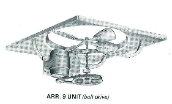
direct and belt drive fan units
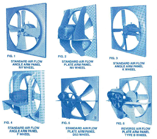
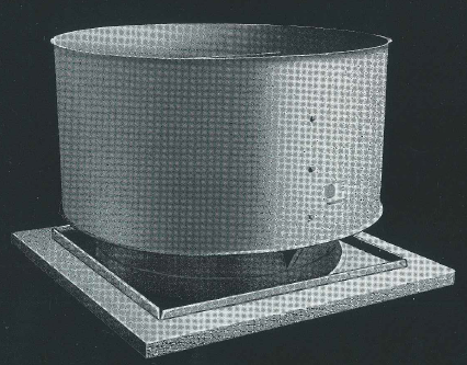
DIRECT DRIVE (Arr. 4) fan panel assemblies (fig. 1,2,3,4) utilize T-frame fool mounted motors as standard with the wheel being mounted on the motor shaft.
BELT DRIVE (Arr. 9) fan panel assemblies (fig. 5, 6) are supplied with heavy duty shafts, antifriction pillow block ball bearings and are designed for use with T-frame foot mounted motors. For adjustment and tensioning of V- belt drives, standard construction provides a slotted motor base plate or unistrut rails. Adjustable motor slide bases are supplied for 284T frame motors and largerventilating.com fanblower.com highpressureblower.net industrialblowerfan.com industrialfanblower.net industrialfanblower.com pressureblower.net northernindustrialsupplycompany.com industrialpressureblower.com tenderall.com chicagoblowercanada.com cbblower.com buffaloblower.com buffalofan.com nis-co.com canadianblower.com olegsystems.com canadablower.com abbblower.com acmefan.net industrialblower.net fansandblowers.net americanblower.net barryfan.com cincinnatifan.net canadafans.com barryfan.netpennbarry.net pennfan.net tcffan.com
.
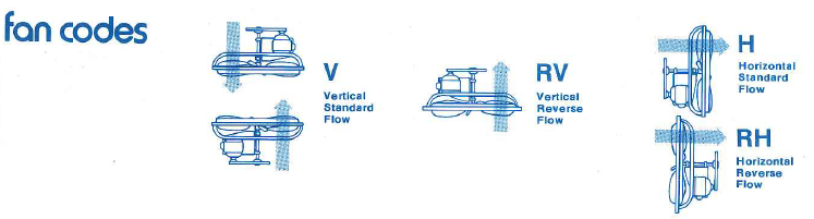
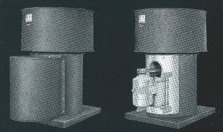
STANDARD FLOW FAN PANEL construction (fig. 1, 2, 3, 4, 5), air entering from the motor side, are all steel and square with flanged edges, having die-formed, deep throated orifices on sizes 18″ thru 54″ (fig. 1, 3, 4) and welded cylindrical bar ring orifices on sizes 60″ thru 120″ (fig. 2, 5). Standard flow may be either Code H or Code V. REVERSE FLOW FANPANEL construction (fig. 6), air entering from the wheel side, has the venturi and wheel reversed. The motor support assembly is located on the discharge side of the unit. Gauges and other construction features are the same as standard flow panels. Reverse flow may be Code RH or RV. VERTICAL AIR FLOW fan assemblies, Codes V and RV, are supplied with two Randall safety locking collars held to the fan shaft with two set screws each on Arr. 9 units. (Under 2-3 /16 shafts one set screw.) They are located between and adjacent to the bearings. The fan wheel end of Arr. 9 fan shafts and motor shafts on Arr. 4 fans are drilled and tapped to accept a hex bolt and retaining plate assembly, assuring positive locking of wheel to shaft. The above modifications are arranged to provide safe operating conditions for both wheel down and wheel up installations. These safety features are standard on all Code V and RV fans.
CHANNEL ARM panel assemblies are all welded consisting of a channel shaped steel bearing base and / or motor support between two vertical rolled structural channels. They are standard for 60″ & 72″ with D53 wheels and 60″ with both NV and type B fan wheels. ANGLE ARM panel assemblies (fig. 1, 3, 4) are all welded consisting of ‘Z’ shaped steel bearing plate and / or motor support between two vertical rolled structural angles for 18″ through 54″. They are standard for all wheel types. PLATE ARM panel assemblies (fig. 2, 5, 6) are all welded plate steel consisting of a horizontal bearing and/or motor base plate with vertical and diagonal support plates positioned below the motor and bearings. This rugged construction is strengthened further in special cases with supports above the motor base welded to the top of the panel (fig. 2). Plate arm construction is standard on sizes 84″ through 120″ with D53 and K wheels, on sizes 66″ through 96″ with NV and type B fan wheels.
centrifugal fan,centrifugal blower,industrial fan,industrial blower,New York Blowers,pressure blower,fan,blowers,ventilator,Twin City
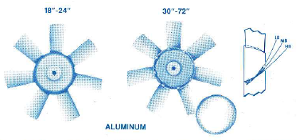
DESIGN 53: D53 fan wheels are designed for belt drive applications, providing high capacity at low speeds and horsepower. Aluminum ventilator blades with steel spiders are furnished on sizes 24″-48″; all steel construction above. The 18″ size is designated Design C.
TYPE K: K fan wheels have manually adjustable blades made of heat-treated, aluminum alloy having high strength to weight ratio and low weight per unit area. Each fan blade is a permanent mold casting having airfoil cross section for maximum efficiency and is positively retained in a blade shank socket of the cast aluminum alloy impeller hub. Refer to factory for performance.
TYPE K: K ventilator wheels have manually adjustable blades made of heat-treated, aluminum alloy having high strength to weight ratio and low weight per unit area. Each fan blade is a permanent mold casting having airfoil cross section for maximum efficiency and is positively retained in a blade shank socket of the cast aluminum alloy hub. Refer to factory for ventilator performance.
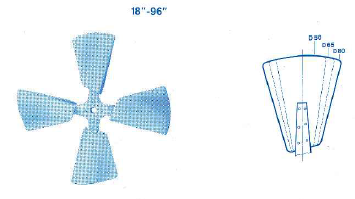
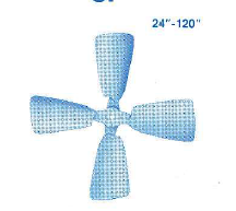
NV, DESIGNS 50-65-80 The rugged NV, four bladed propeller type fan wheel is offered in three blade widths and designed to blanket a wide performance range for direct driven ventilator applications. It is the most economical selection for direct driven fans but is also well suited for severe duty belt driven fan applications. Construction consists of heavy steel blades, and rugged fabricated steel spiders with support gussets. Spiders are ’A” on sizes 24″ thru 54″, %” on sizes 60″ thru 72″ and one-piece cast steel on sizes 84″ and 96″.
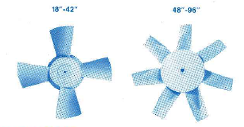
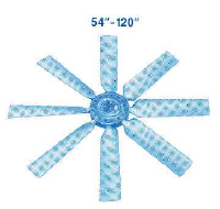
TYPE B, LB-MB-HB Axial flow fan wheels are offered with three different blade angles having a large hub to wheel diameter ratio. The LB-MB-HB, low-medium-high blade angle wheels respectively, provide a wide range of high efficiency direct drive performance selections when requirements exceed the NV capabilities. The MB, medium (standard) angle ventilator wheel is offered for belt driven applications to expand the range of air and pressures above those available with D53 and NV wheels. Sizes 18″ thru 42″ steel fan wheels have.
Die-formed fan blades welded to a streamlined die-formed hub. Sizes 48″ thru 96” steel ventilator wheels have die-formed blades and blade reinforcing plate with blades welded between two parallel circular discs and integral hub. Aluminum wheels size 18″ and 24″, are a one-piece cast construction with an integral spinner. Sizes 30″ thru 72″ aluminum wheels are a one-piece casting with removable spinner supplied with reverse flow fan panels.
STYLE “H” SKY-VENT POWER ROOF VENTILATORS
for filtered supply air
Style “H” filtered supply roof ventilators, for clean makeup air, are available in nine standard sizes from 18″ through 72″ with capacities up to 58,000 CFM. Special ventilator designs are also available for fan sizes 84″-120″ with capacities to 210,000 CFM. Filtered supply roof ventilators incorporate the same high quality dependable construction features utilized in the standard Style “H” Sky-Vent with the respective sizes of each having identical stack, curb cap and fan assemblies. The optional features listed on page 7 are also available on the filtered Sky-Vent. All filter heads are shipped separate from the stack assemblies and are split for ease of handling on sizes 42″ and larger.
filtered mushroom fan heads feature…
1 Filter options of high or low velocity, cleanable or throwaway types. 2 Channel-type filter racks welded to the head tube frame, firmly supporting the filters in a horizontal position on sizes 24″ and larger and vertically on size 18”, utilizing fully the total filtering surface. 3 Filter removal through an end “dropout” position in each rack, with the final close-off filter securely fastened by convenient easy-opening, thumb screws and retaining clips. 4 Internal frame of all welded steel square tubing for high wind and snow loads. 5 Exterior skin of galvanized steel joined with Pittsburgh lock seams.
6 Three quarter inch mesh bird screen inside the head, vertical position, providing protection against entry of birds and debris when filters are removed for cleaning. 7 Exterior of head sprayed with heavy asphalt coating (Trade name: Spraycor) for corrosion and moisture resistance. 8 Access through the head to motors and drives. A. Fan sizes 18” through 42″ are hinged from the stack and held with positive locking support struts for safe and easy access. B Fan sizes 48″ and larger are bolted to the stack and are readily , serviced through a removable section of bird screen after-removing several filter cells.
NOTE: An allowance for static pressure loss through the desired type of filter shoud be added to the external static pressure requirement when selecting a ventilator from the rating tables. Hi-velocity, cleanable filters are recommended for maximum capacity with minimum pressure drop. Hi-velocity throw-away filters are available, but will require increased pressure loss allowance, for a given capacity, than with cleanable types. The listed maximum filter capacities for low and high velocity filters are based on filter manufacturers recommended air velocities of 350 and 520 FPM respectively.
STYLE “H” FILTERED SKY-VENT FAN
FAN size
max.capacity (CFM)
No. FILTERS Low Vel.
Hi-Vel. Size
Position 18 2.560 3840 4 16x20x2 Vertical 24 5.120
7680 8 16x20x2 Horizontal 30
8.960 13.440 14 16x20x2 Horizontal 36 11.200 16.800 14 20x20x2 Horizontal 42 14.400 21.600 18 16x25x2 Horizontal 48 17.600 26.400 22 16x25x2 Horizontal 54 22.000 33.000 22 20x25x2 Horizontal 60 28.000 42.000
28 20x25x2 Horizontal 72 38.400 57.600 48 20x20x2 Horizontal
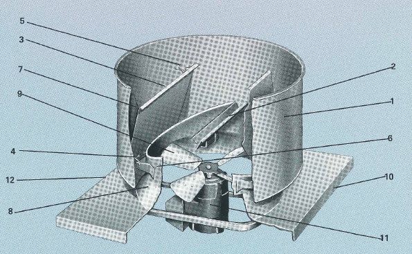
FAN WHEEL DESIGN
The various wheel designs shown below are incorporated into the Direct Drive and Belt Drive ventilators.

Design T Four bladed propeller type with die-formed aluminum fan blades riveted to steel spider. Offered in sizes 12″, 16″, 18″ and 24″ with direct drive ventilators only. Type F: F fan wheels have manually adjustable airfoil fan blades molded of glass fiber reinforced polypropylene, and seated at increments in pressure cast aluminum fan wheel hubs. A wide range of air flow capacities and pressures is available from sizes 24″ to 48″ by using the appropriate number of blades, at most efficient blade setting, for belt or direct drive. Refer to factory for fan performance. Design 53 Engineered for belt drive applications providing large air deliveries at low speeds and horsepowers. Most economical selection for Arr. 9 units, sizes 24″ to 72″. Offered for sizes 24″-48″ with aluminum fan blades and steel spider, and 54″-72″ with all steel construction with 1A” die-formed spider (%” on 60″-72″) supported with gusset welded to the spider and hub. Die-formed aluminum blades also available. All have four die-formed fan blades riveted to spider. Sizes 84″ to 120″, Design 53 wheels are 5-bladed and extend the capacity range for a single fan to 210,000 CFM. The fan blades are welded between two parallel hub discs and supported with welded blade stiffeners at the hub and bolted pipe struts near the periphery. Design C Four bladed propeller type with die-formed aluminum blades riveted to a one piece die-formed spider (aluminum for 1140 RPM. and steel for 1725 RPM.) and steel hub. Available on 18″ direct drive, (Arr. 4) ventilators. Type K: K fan wheels, sizes 54″ to 120″, have manually adjustable blades made of heat-treated, aluminum alloy having high strength to weight ratio and low weight per unit area. Each blade is a permanent mold casting having airfoil cross section for maximum efficiency and is positively retained in a blade shank socket of the cast aluminum alloy hub. Refer to factory for performance. NV, Designs 50-65-80 The rugged NV, four bladed propeller type fan wheel is offered in three blade widths and designed to blanket a wide performance range for direct driven fan applications. It is the most economical selection for direct driven fans but is also well suited for severe duty belt driven applications. Construction consists of heavy steel blades, and rugged fabricated steel spiders with support gussets. Spiders are 1A” on sizes 24″ thru 54″, %” on sizes 60″ thru 72″ and one-piece cast steel on sizes 84″ and 96″. Type B, LB-MB-HB Axial flow wheels are offered with three different blade angles having a large hub to wheel diameter ratio. The LB-MB-HB, low-medium-high fan blade angle wheels respectively, provide a wide range of high efficiency direct drive performance selections when requirements exceed the NV capabilities. The MB, medium (standard) angle wheel is offered for belt driven applications to expand the range of air and pressures above those available with D53 and NV wheels. Sizes 18″ thru 42″ steel wheels have die-formed blades welded to a streamlined die-formed hub. Sizes 48″ thru 96″ steel wheels have die- formed fan blades and blade reinforcing plate with blades welded between two parallel circular discs and integral hub. Aluminum wheels size 18″ and 24″, are a one-piece cast construction with an integral spinner. Sizes 30″ thru 72″ aluminum wheels are a one-piece casting with removable spinner supplied with reverse flow fan panels. Note: Fan wheel construction in special metals not covered on this page should be referred to your local “Canada Blower” Engineer for availability.
Canada Blower Commercial Axial Fans
Breezeway (BZW) Axial Propeller Panel Fans
Domex Axial (DXA) Flow Exhausters (DAE)
Hi-Ex (HX) Vertical Discharge Air Exhausters
LWP Series Large Wall Propeller Fans
Powered Airette (AE) Exhaust or Supply Roof Flow Ventilators
RAU and RAUMO Series Roof Axial Upblast Fans
SWP Series Axial Propeller Panel Fans
Canada Blower Specialty Commercial Fans
Gravity Airette (AEG) Hooded Roof Ventilators
Gravity Ventilators (GRV)
PennHouse (PH) Roof Mounted Air Intake or Exhaust Housing Ventilation Unit
PennHouse Ventilators (PHHW) Miami-Dade Approved
Roof Curbs (RC)
Weather Caps (WC) Pressure Relief Ventilators
associated ventilating equipment
industrial blower,industrial fan,industrial ventilator,centrifugal blower,centrifugal fan,centrifugal ventilator,pressure blower
BREEZO Small “packaged” fans with features as above — sizes 8” to 24” — capacities 500 to 5,600 CFM and up to 1/2” S.P. Refer FP-100.
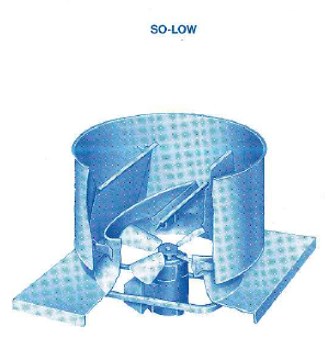
SO-LOW Style V, “So-Low” Skyvent is a low-silhouette, factory assembled, roof ventilator of upblast design which fits directly on your roof curb. Direct or belt drive propeller or axial fan and motor combinations can be used in wind band/discharge damper assembly which is constructed to withstand hurricane force winds. Can be mounted on flat or pitched roofs. Capacities to 130,000 CFM.
FILTER-VENTS Eight sizes (Models No. 1 to No. 8) — capacities to 5,000 CFM — filtered ventilation for in-plant offices and equipment rooms — draw thru and blow thru — hi-velocity cleanable filters with removal door — package construction and prepunched mounting flanges for easy installation. Refer FP-700.
SO-LOW Style V, “So-Low” Skyvent is a low-silhouette, factory assembled, roof ventilator of upblast design which fits directly on your roof curb. Direct or belt drive propeller or axial fan and motor combinations can be used in wind band/discharge damper assembly which is constructed to withstand hurricane force winds. Can be mounted on flat or pitched roofs. Capacities to 130,000 CFM.
OTHER CANADA BLOWER FANS FOR VENTILATION
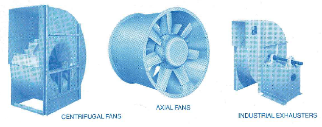
CENTRIFUGAL FANS • TYPE BL Wheel (shown) is widely used in ventilating systems and process applications for capacities to 700,000 CFM and static pressures to 20″ W.G. With backwardly curved blades and fixed, curved inlet vanes in streamlined inlet bell, matched to outer wheel flange, the BL fan provides high efficiencies, stable fan performance, and low noise levels over a broad fan operating range. Available in SWSI or DWDI fan arrangements for belt or direct drive; in 46 sizes from 12%” diameter to 1083/4″ diameter. • TYPE BL-AEROFOIL, for applications where an Aerofoil fan wheel is preferred, combines all the features of the BL with double thickness fan blades; for capacities to 660,000 CFM and static pressures to 12″ W.G. AXIAL FANS For many air moving jobs a lightweight, compact axial fan may be the best choice in either direct drive or belt driven. Canada Blower gives you three (3) choices: • TYPE S ADJUSTAX (shown) features fanh blades that can have their pitch adjusted to exactly match capacity and pressure requirements and make on-the-job adjustments later to compensate for system changes. Unique “O-ring” design facilitates system balancing without requiring access to the inlet. Capacities range from 3,000 to 400,000 CFM, total pressures from 1″ to 20″. • TYPE B fan offers three (3) different fan blade angles in fixed pitch wheels of steel or aluminum construction for maximum efficiency of direct or belt drive performance. A wide variety of fan accessories are available for industrial ventilation applications. Capacities to 330,000 CFM, total pressures to 5″ W.G. • VPS (controlled pitch) for in-flight control of blade pitch on variable volume ventilation systems. Needs only 25 psi to activate blade adjusting mechanism. Capacities to 225,000 CFM, total pressures to 12″ W.G. Bulletin F-315 INDUSTRIAL EXHAUSTERS The MW (shown) is the work horse of industrial ventilation. Three (3) standard fan wheel designs are available for your specific application. • TYPE MW (material handling blower wheel) for dust, abrasive material, granular, etc. • TYPE OW (open radial blower wheel) for fibrous materials. • TYPE AW (air handling radial fan wheel) for maximum efficiency on cleaner air; for capacities to 85,000 CFM, static pressures to 20″ W.G., temperatures to 850 degrees F. • TYPE HW blower wheel, high pressure fan exhausters for capacities to 27,000 CFM and static pressures to 40″ W.G., is available in eight (8) sizes. • TYPE FRP MW, industrial radial exhausters built of fiberglass reinforced plastic with wheel hubs of steel encapsulated in FRP, is used for corrosive gases. Capacities to 43,000 CFM and static pressures to 20″ W.G.
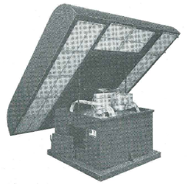
STYLE “V” SKY-VENT ROOF FAN
STANDARD SIZES 15″ through 72″ Fan Wheel Diameters CAPACITIES 2200 through 130,000 CFM. RUGGED FAN CONSTRUCTION for: • Hurricane Force Winds. • Corrosive Atmospheres. Canada Blower Style “V” Sky-Vent Power Roof Ventilators, with their outstanding design features provide clear evidence of the continued leadership of “Canada Blower” in the engineering development and manufacture of ventilating fan “packages” for industrial and commercial ventilation. During the past several years a tremendous change has taken place in ventilation demands. Business establishments have been and are being confronted with rapidly increasing requirements for plant ventilation to attract and retain employee personnel. Demands for improved working conditions coupled with plant management recognition that improved ventilation reduces fatigue, increases production, and eliminates work stoppages, are among the principal factors underlying the demand. The desirability of being able to locate or utilize “package” ventilating equipment in plant areas where side-wall locations were not available or desirable – to effectively ventilate a specific plant area not adjacent to outside walls without expensive or extensive duct work – or to ventilate buildings with equipment located on roof areas without using up valuable internal space, has resulted in a rapidly increasing demand for “Power Roof Ventilators”. This demand has been greatly stimulated by the increasing demand for plant flexibility as exemplified by the automotive industry. Formerly bulky central ventilating systems with extensive duct work were widely used. Now with the necessity for plants lending themselves to major rearrangement of production equipment when changes in models, or products takes place, the utilization of power roof ventilators is rapidly increasing. Recognizing this demand, the Canada Blower Company engaged in an intensive test and design program to greatly increase the size and capacity ranges that could be provided in power roof ventilator fans. Subsequent releases incorporating Breezos, Design 53 Belt-Airs, Design 80, 65 and 50 NV Fans, Type “B” Fans and now, Types K and F, covered a size range from 15″ through 72″ wheel diameters with capacities from 2200 to 130,000 CFM at pressures from free delivery to 1″ or higher static pressures. Availability of “package” fan units for either direct or V-belt drive, shipped completely assembled with motor drive for easy installation by customer, made ventilation applications, formerly economically impossible or attainable only at extremely high cost, possible at costs well within economic consideration. High fan efficiencies resulted in the lowest possible operating costs. Fan maintenance expense was held to a minimum as a direct result of the rugged and outstanding ventilator design features. The high volumes of air required for adequate ventilation of large plants can easily and most economically be handled with “Canada Blower” Sky-Vents. It costs a great deal to cut through existing structures and build up curbed roof openings or to provide such curbed roof openings in new construction. With the high capacity Canada Blower Sky-Vent, the number of roof openings can be minimized and initial equipment cost held at the lowest possible level. At the same time the rugged “Canada Blower” construction far out-values the lighter gauge construction provided by some other fan manufacturers.
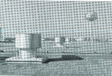
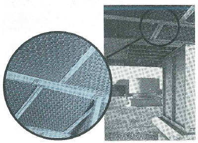
Typical installation of Sky-Vents in a large automotive plant utilizing spot ventilation in a one or two story modern plant design. Used in place of former bulky central ventilating systems with extensive ductwork utilized in plants of multi-story design. In this particular plant all roof opening sizes were standardized and special over-size curb sheet design was required on Style “V” Sky-Vent exhaust fan units. They represent the most quiet method to exhaust warm or contaminated air from your plant area. MOTOR SUPPORT CONSTRUCTION.. .A sturdy angle or channel arm construction, as illustrated below, is standard on the So-Low Sky-Vent fan panels for all sizes with D53 wheels, and up through size 60″ with types NV and B ventilator wheels. In sizes 66″ and 72″, using the latter two wheels, a heavy plate arm construction is standard. Published ratings requiring motors which exceed those shown below for angle or channel arm construction with type B wheels will also have plate arm motor supports. Motor support construction for Arr. 9 ventilators with D53 and NV fan wheels having larger motors than their listed maximums but which do not exceed the type B maxi- mums, may be angle or channel or plate arm depending on the rating, application and fan installation requirements.
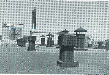
The ventilation of the entire machine room at the Wausau Paper Mills Company, Brokaw, Wisconsin plant, is typical of installations requiring the rugged construction of Canada Blower Arr. 9 Type “AF” Sky-Vent fans. This application required 1,000,000 CFM divided equally between supply and exhaust.
STYLE “V” SO-LOW SKY-VENT FAN
The Style V So-Low Sky-Vent is a low-silhouette, factory assembled package roof ventilator constructed to withstand hurricane force winds and fit directly onto your roof curb. These roof ventilators are excellent for both general ventilation and spot ventilation of trouble areas. With roof fans there is nothing that will interfere with crane ways or general plant operations. The vertical fan discharge jets exhausted air or fumes above the roof level preventing air recirculation into supply systems and possible damage to roof. The simple and rugged construction means a sturdy unit with low maintenance and the low silhouette is especially suited to todays modern architecture. All units are designed to a minimum of 1800 fpm velocity through the stack to prevent rain or snow from entering the building. Many years of Canada Blower engineering and manufacturing experience have been utilized to offer the most economical, the most efficient.
MAXIMUM MOTORS WITH STANDARD ANGLE OR CHANNEL ARM MOTOR SUPPORT
* size
16 18 24 30 36 42 48 54 60 66 72 Arr.4 NV.T. Type B
56 145T 184T 215T 215T 286T 286T 326T 326T
P.A. P.A. Arr. 9
D 53
– – 145T 182T 184T 213T 213T
213T 254T 256T 284T NV – – 145T 182T 184T 254T 215T
256T 286T PA PA TYPE B
– – 145T 213T 215T 254T 256T 256T 286T PA PA
blower,fan,industrial,process,OEM,ventilator,centrifugal,radial,scroll cage,New York Blower,Twin City,NYB
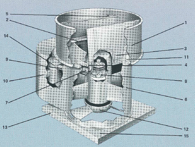
1. WIND BAND — Heavy gauge galvanized steel; rolled with flanged edges for extra stiffness. 2. RAIN GUTTER — Heavy steel, hot dipped galvanized after fabrication, bolted in place with cadmium plated hardware. Bolted construction provides access to remove wheel or motor from the roof level. Also adds structural stiffness to the stack. 3. AUTOMATIC DAMPERS—Open to outside of the airstream offering minimum resistance to air flow. The Blades are made of joggled aluminum sheet, double thickness to prevent warping under repeated opening and closing. 4. DAMPER BEARINGS—Trouble free oilite bushings imbedded in a solid block of aluminum and mounted outside of air or fumes being exhausted. 5. DAMPER STOPS —To insure straightness of damper edge and positive sealing when closed, point stops have been installed on sizes 16″ through 48”. On sizes 54″ to 72”, full length angle stops are provided as standard. 6. STACK — Heavy gauge galvanized steel. Insures true vertical discharge. 7. GUSSETS — Extra heavy gauge galvanized steel to rigidly fasten wind band to the stack. 8. VENTURI — Streamlined venturis, die formed on sizes 16” to 54” and welded ring on sizes 60” to 72″, closely shrouding fan wheel for minimum noise and maximum efficiency. 9. HEAVY DUTY PROPELLER FAN — Variety of designs available to meet most ratings required. All fans are proved rugged and efficient from many years of industrial usage in our standard propeller fan line. 10. ROOF CURB SHEET — Heavy gauge steel with flanged edges to simplify flashing to roof curbs and insuring leak proof installation. 11. MOTOR — Totally enclosed, air-over construction with class B insulation is standard. Special motors are readily available. 12. FINISH — The entire unit except inside of stack, dampers, fan assembly and motor is sprayed with a thick asphalt coating (Tradename; Spraycor) for corrosion and moisture resistance. The inside of the curb sheet and fan assembly is coated with a bitumastic asphalt base, moisture resistant paint.
POWER ROOF VENTILATORS
AF TYPE STYLE “V” SKY-VENT FANS
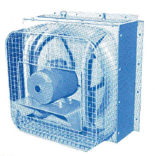
The AF type Canada Blower Sky-Vent was developed to meet the demand by industry to incorporate the rugged, trouble free and highly efficient designs of Canada Blower vaneaxial and tubeaxial fans into a line of Power Roof Ventilators capable of handling exhaust applications beyond the scope of conventional light-duty ordinary design roof ventilators. In the AF Type Sky-Vent the Canada Blower standard axial flow fan housing is incorporated into the unit and actually represents the stack to which a separate damper head and curb sheet are attached. The belt drive, arrangement 9, ventilator is ideal for handling corrosive and /or explosive fumes because the shaft, bearings, V-belt drive and motor are completely isolated from the air or fumes being removed. The heavy gauge, continuously welded protective belt fairing is completely air tight. A weather tight, easily removable cover protects both motor and drive from all weather conditions. Motor, drive and bearings can readily be serviced from the roof level by removing the weather cover. The direct drive, arrangement 4 fan was designed from our standard tubeaxial fan line to provide high capacity, efficient and quiet roof units with the ruggedness inherent in the standard axial fan line. Because of the simple rugged construction, the arrangement 4 unit is most economical when the fume to be exhausted is non corrosive. Totally enclosed, air over motors are supplied as a standard on all arrangement 4 units. AF TYPE DAMPER FI EADS . . . Flanged fan damper head assemblies and curb caps, in standard AF type sizes, are available assembled without a fan, or separately for design flexibility using Canada Blower Vaneaxial fans.
POWER ROOF VENTILATORS
1. WIND BAND — Heavy gauge galvanized steel; rolled with flanged edges for extra stiffness. 2. RAIN GUTTER — Heavy steel, hot dipped galvanized after fabrication, bolted in place with cadmium plated hardware. Bolted construction provides access to remove wheel or motor from the roof level. Aiso adds structural stiffness to the stack. 3. AUTOMATIC DAMPERS—Open to outside of the airstream offering minimum resistance to air flow. The Blades are made of joggled aluminum sheet, double thickness to prevent warping under repeated opening and closing. 4. DAMPER BEARINGS—Trouble free oilite bushings imbedded in a solid block of aluminum and mounted outside of air or fumes being exhausted. 5. DAMPER STOPS—To insure straightness of damper edge and positive sealing when closed, point stops have been installed on sizes 15″ through 48”. On sizes 54” to 72”, full length angle stops are provided as standard. 6. STACK — Identical to Canada Blower’s standard line of ruggedly designed tube and vane axial flow fan housings. 7. PROTECTED BELT FAIR ING — Heavy gauge steel continuously welded, providing an air-tight housing isolating the V-belt drive, bearings and shaft out of the contaminated air stream. 8. FAN BEARINGS — Heavy duty self aligning, flange mounted cast iron pillow block ball bearings for continuous trouble free operation. Grease fittings are brought to the outside of the housing but under the weather tight cover for easy maintenance. 9. BELT TENSION ADJUSTMENT — Screw type arrangement for easy and positive adjustment of V-belt drive. Note also that all adjustments can be made from the roof level. 10. MOTOR COVER — Weather tight protective cover furnished as standard. 11. GUSSETS — Extra heavy gauge galvanized steel to rigidly fasten wind band to the stack. 12. HEAVY DUTY FAN WHEEL — A variety of rugged wheel designs are available to effectively blanket a wide performance range. The efficient and trouble free performance record of these wheel designs has long been an established fact in our standard propeller fan and axial flow fan lines. 13. ROOF CURB SHEET — Heavy gauge steel with flanged edges to simplify flashing to roof curb and insuring leak proof installation. 14. MOTOR— Open, totally enclosed fan cooled or explosion proof fan cooled motors are utilized with this design. 15. FINISH—The entire unit except inside of stack, dampers, fan assembly and motor is sprayed with a thick asphalt coating (Tradename: Spraycor) for corrosion and moisture resistance. The inside of the curb sheet and fan assembly is coated with a bitumastic asphalt base, moisture resistant paint.
In an Arrangement 4 direct drive Type AF unit (motor mounting shown above) the stack height is shorter than in an Arrangement 9 Type AF unit. Also a totally en-closed, air-over motor can be used if desired in lieu of the more ex-pensive totally enclosed fan cooled construction.
Special Design and Construction Features Available…
STYLE V-SoLow Fans
• STYLE V-AF Fans
FAN ROOF CURBS
SURFACE MOUNT STYLE FOR WOOD, STEEL OR CONCRETE DECKS
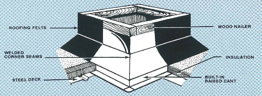
Canada Blower Sky-Vent Power Roof Ventilators are made with a one piece perimeter style flanged roof curb cap designed to fit over the roof curbs .n. The roof curbs are made of heavy gauge galvanized steel with unitized seam welded construction with 1-1/2″ thick 3 lb. density fiberglass insulation and are topped with a wood nailer strip for fastening the roofing felts and bolting down the Sky-Vent. Available for fast delivery, they can be shipped to the job site well ahead of the Sky-Vent roof ventilators so that they may be installed when the roof is being placed. The outside curb dimensions are sized for 3/4″ clearance between the Sky-Vent curb cap on each side to allow for the built up of the roofing felts. Optional Features include other heights, extended base plate for damper installation, heavier gauges and liners.
Disconnect (Safety) Switches Non-fusible and fusible Nema Type 3R rain tight enclosure disconnect switches are available, normally mounted on the wind band for easy access.
Factory Wiring JIC Spec., weather proof factory wiring can be supplied, to minimize installation costs, from the motor to the disconnect and from the disconnect to 4′ below the curb cap.
Foundation Bolt Holes Holes in the curb cap can be provided for foundation hold down bolts upon request, Specify if specific position and bolt centers are required.
Aluminium Construction Spark resistant construction consisting of aluminum bladed propeller wheels or cast, all aluminum, axial flow wheels is available. All aluminum construction of both So-Low and AF type Sky-Vents can also be supplied. Refer to your local ”Canada Blower” FRP Construction Fiberglass Reinforced Polyester (FRP) corrosion resistant construction Is available in both So-Low and AF type designs through size 54″. Performance data and critical dimensions are as listed in this bulletin with most features of steel units being available. Special Coatings Protective coatings for corrosive exhaust fumes or atmospheres are available including a synthetic vinyl plastic and a catalytic epoxy, both air dried. Contact your local “Canada Blower” Engineer for availability of other special coatings and paints.
FUSIBLE LINK FIRE RELEASE MECHANISM
A fusible link fire release mechanism is frequently specified to meet requirements of fire insurance companies. This device is readily available for all Style “V” units. It allows smoke and heat to quickly escape in the event of fire minimizing damage to structural steel so prevalent in modern plant design. The fusible link is designed to release the mechanism at a temperature of 212°F and provide positive opening of the dampers even in the event of a power failure.